FREE SHIPPING ON ORDERS OVER $99! Click for Details
SAVE UP TO 75% ON DISCONTINUED GRAB BARS: Straight, Angled, Corner, Wall to Floor, & Flip Ups
FREE SHIPPING ON ORDERS OVER $99! Click for Details
SAVE UP TO 75% ON DISCONTINUED GRAB BARS: Straight, Angled, Corner, Wall to Floor, & Flip Ups
ADA Grab Bar Requirements for Shower Stalls, Bath Tubs, and Toilet Stalls
CONSULT MANUFACTURER’S INSTALLATION INSTRUCTIONS FOR PROPER INSTALLATION OF SPECIFIC PRODUCT.
See also ADA Requirements for Seats
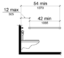
Side Wall - The side wall grab bar shall be 42 inches (1065 mm) long minimum, located 12 inches (305 mm) maximum from the rear wall and extending 54 inches (1370 mm) minimum from the rear wall.
Side Wall 
Rear Wall 
Rear Wall - The rear wall grab bar shall be 36 inches (915 mm) long minimum and extend from the centerline of the water closet 12 inches (305 mm) minimum on one side and 24 inches (610 mm) minimum on the other side.
EXCEPTIONS: 1. The rear grab bar shall be permitted to be 24 inches (610 mm) long minimum, centered on the water closet, where wall space does not permit a length of 36 inches (915 mm) minimum due to the location of a recessed fixture adjacent to the water closet.
Transfer Type Shower Compartments - Transfer type shower compartments shall be 36 inches (915 mm) by 36 inches (915 mm) clear inside dimensions measured at the center points of opposing sides and shall have a 36 inch (915 mm) wide minimum entry on the face of the shower compartment. Clearance of 36 inches (915 mm) wide minimum by 48 inches (1220 mm) long minimum measured from the control wall shall be provided.

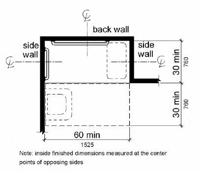
Standard Roll-In Type Shower Compartments - Standard roll-in type shower compartments shall be 30 inches (760 mm) wide minimum by 60 inches (1525 mm) deep minimum clear inside dimensions measured at center points of opposing sides and shall have a 60 inches (1525 mm) wide minimum entry on the face of the shower compartment.
608.2.2.1 Clearance. A 30 inch (760 mm) wide minimum by 60 inch (1525 mm) long minimum clearance shall be provided adjacent to the open face of the shower compartment.
EXCEPTION: A lavatory complying with 606 shall be permitted on one 30 inch (760 mm) wide minimum side of the clearance provided that it is not on the side of the clearance adjacent to the controls or, where provided, not on the side of the clearance adjacent to the shower seat.

Alternate Roll-In Type Shower Compartments - Alternate roll-in type shower compartments shall be 36 inches (915 mm) wide and 60 inches (1525 mm) deep minimum clear inside dimensions measured at center points of opposing sides. A 36 inch (915 mm) wide minimum entry shall be provided at one end of the long side of the compartment.

608.3 Grab Bars - Grab bars shall comply with 609 and shall be provided in accordance with 608.3. Where multiple grab bars are used, required horizontal grab bars shall be installed at the same height above the finish floor.
EXCEPTIONS:
1. Grab bars shall not be required to be installed in a shower located in a bathing facility for a single occupant accessed only through a private office, and not for common use or public use provided that reinforcement has been installed in walls and located so as to permit the installation of grab bars complying with 608.3.
2. In residential dwelling units, grab bars shall not be required to be installed in showers located in bathing facilities provided that reinforcement has been installed in walls and located so as to permit the installation of grab bars complying with 608.3.
Transfer Type Shower Compartments - In transfer type compartments, grab bars shall be provided across the control wall and back wall to a point 18 inches (455 mm) from the control wall.

Figure 608.3.2 Grab Bars for Standard Roll-In Type Showers
Alternate Roll-In Type Shower Compartments - In alternate roll-in type shower compartments, grab bars shall be provided on the back wall and the side wall farthest from the compartment entry. Grab bars shall not be provided above the seat. Grab bars shall be installed 6 inches (150 mm) maximum from adjacent walls.

Figure 608.3.3 Grab Bars for Alternate Roll-In Type Showers
608.4 Seats. A folding or non-folding seat shall be provided in transfer type shower compartments. A folding seat shall be provided in roll-in type showers required in transient lodging guest rooms with mobility features complying with 806.2. Seats shall comply with 610.
Grab Bars in Tub Requirements
Back Wall. Two grab bars shall be installed on the back wall, one located in accordance with 609.4 and the other located 8 inches (205 mm) minimum and 10 inches (255 mm) maximum above the rim of the bathtub. Each grab bar shall be installed 15 inches (380 mm) maximum from the head end wall and 12 inches (305 mm) maximum from the control end wall.
Control End Wall. A grab bar 24 inches (610 mm) long minimum shall be installed on the control end wall at the front edge of the bathtub.

Figure 607.4.1 Grab Bars for Bathtubs with Permanent Seats
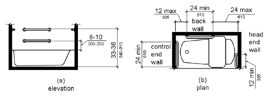
Back Wall. Two grab bars shall be installed on the back wall, one located in accordance with 609.4 and other located 8 inches (205 mm) minimum and 10 inches (255 mm) maximum above the rim of the bathtub. Each grab bar shall be 24 inches (610 mm) long minimum and shall be installed 24 inches (610 mm) maximum from the head end wall and 12 inches (305 mm) maximum from the control end wall.
Control End Wall. A grab bar 24 inches (610 mm) long minimum shall be installed on the control end wall at the front edge of the bathtub.
Head End Wall. A grab bar 12 inches (305 mm) long minimum shall be installed on the head end wall at the front edge of the bathtub.

Figure 607.4.2 Grab Bars for Bathtubs with Removable In-Tub Seats
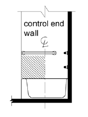
Controls. Controls, other than drain stoppers, shall be located on an end wall. Controls shall be between the bathtub rim and grab bar, and between the open side of the bathtub and the centerline of the width of the bathtub. Controls shall comply with 309.4.

Figure 607.5 Bathtub Control Location
CONSULT MANUFACTURER’S INSTALLATION INSTRUCTIONS FOR PROPER INSTALLATION OF SPECIFIC PRODUCT.